
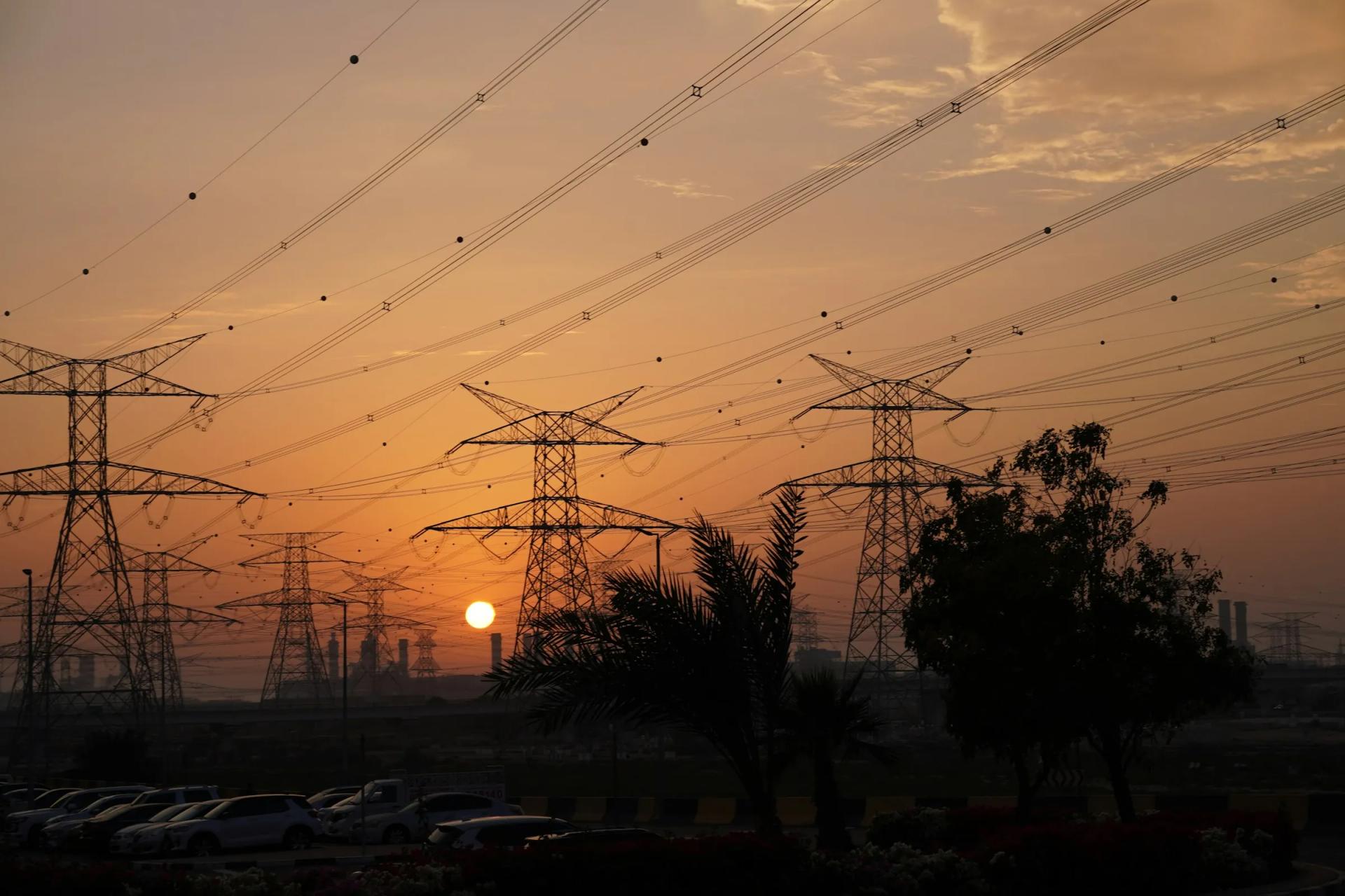
The facility
Capacity you cancontract now.
Existing, powered infrastructure in the UAE, being converted into AI capacity on a staged timeline. What remains is fit-out — scoped to your platform, not ours.
5 MW
Available today
On an existing substation
10–15 MW
Expansion pathway
Subject to utility approval
Tier III
At launch
Concurrently maintainable design
Tier IV
Target, month six
Fault-tolerant end state
The critical path
The long-lead itemsare already behind us.
A new AI data centre spends most of its timeline on things that are not compute. On this site, those are done.
| Critical-path item | Typical greenfield | This site today |
|---|---|---|
| Site & buildings | Typical:Land, design, permits, construction | Complete — 2 × 1,200 sqm high-standard buildings |
| Grid power | Typical:Utility application and connection, often the longest lead item | Complete — substation in place, 5 MW available |
| Power resilience | Typical:Procure and install generators, UPS / BESS | In place — backup generators and battery backup |
| Cooling plant | Typical:Chiller procurement and installation | In place — AC, chillers and backup cooling |
| Licensing | Typical:Entity setup and activity licensing | Initial trade licence approval issued |
| GPU fit-out & commissioning | Typical:After all of the above | Next step — scoped to your platform and timeline |
Investment goes into compute and commissioning, not concrete.
Why the critical path matters
A new AI data centre spends most of its timeline on things that are not compute: land, buildings, a grid connection, power resilience, a cooling plant, a licence. On this site, those are done. The table is the typical greenfield path against where this site stands today.
 Render
Infrastructure in place
Already built.Already powered.
Buildings, substation, cooling plant and standby power are on site. Direct liquid cooling is added at fit-out.
Facilities
Two 1,200 sqm warehouses built to a high standard, ready for data-hall conversion.
Power
Dedicated substation. 5 MW available, with a pathway to 10 MW and potentially 15 MW.
Cooling
AC and chillers in place with backup units. Direct liquid cooling is added at fit-out for high-density GPUs.
Standby generation
Backup generators providing on-site power resilience.
Battery / UPS
Battery backup for ride-through and clean transfer to generation.
Secure campus
A single-tenant-capable site with perimeter control for sovereign workloads.
Resilience programme
Tier III at launch.Tier IV by month six.
Both are targets. The design is built to them; the certificate is issued by the Uptime Institute, not by us.
- Topology
- N+1 power and cooling components; concurrently maintainable
- Distribution
- Dual-path delivery, one active path
- Maintenance
- Any component serviced without an IT outage
- Certification
- Uptime Institute Tier III Design & Constructed Facility — target
- Topology
- 2N or 2(N+1) fault-tolerant power and cooling
- Distribution
- Dual active, compartmentalised paths
- Fault tolerance
- A single failure absorbed with no IT impact
- Certification
- Uptime Institute Tier IV Design & Constructed Facility — target
How contracted IT load is sized
A staged programme, so capacity goes live early without compromising the end state. Both certifications are targets: the design is built to them, and the certificate is issued by the Uptime Institute, not by us.
Under a 2N topology, contracted IT load is sized against redundant capacity. The IT megawatt allocation per phase is agreed with each partner.
Certification roadmap — targets
- Uptime Tier III → IV
- ISO/IEC 27001
- ISO/IEC 27017 / 27018
- ISO 22301
- ISO 9001 / 14001 / 50001
- SOC 1 & SOC 2 Type II
- PCI DSS, as required
- UAE IA Standard & PDPL
None of these is held today. Each is a target the facility and its operations are being built to, and each will be published with its certificate when it is issued.
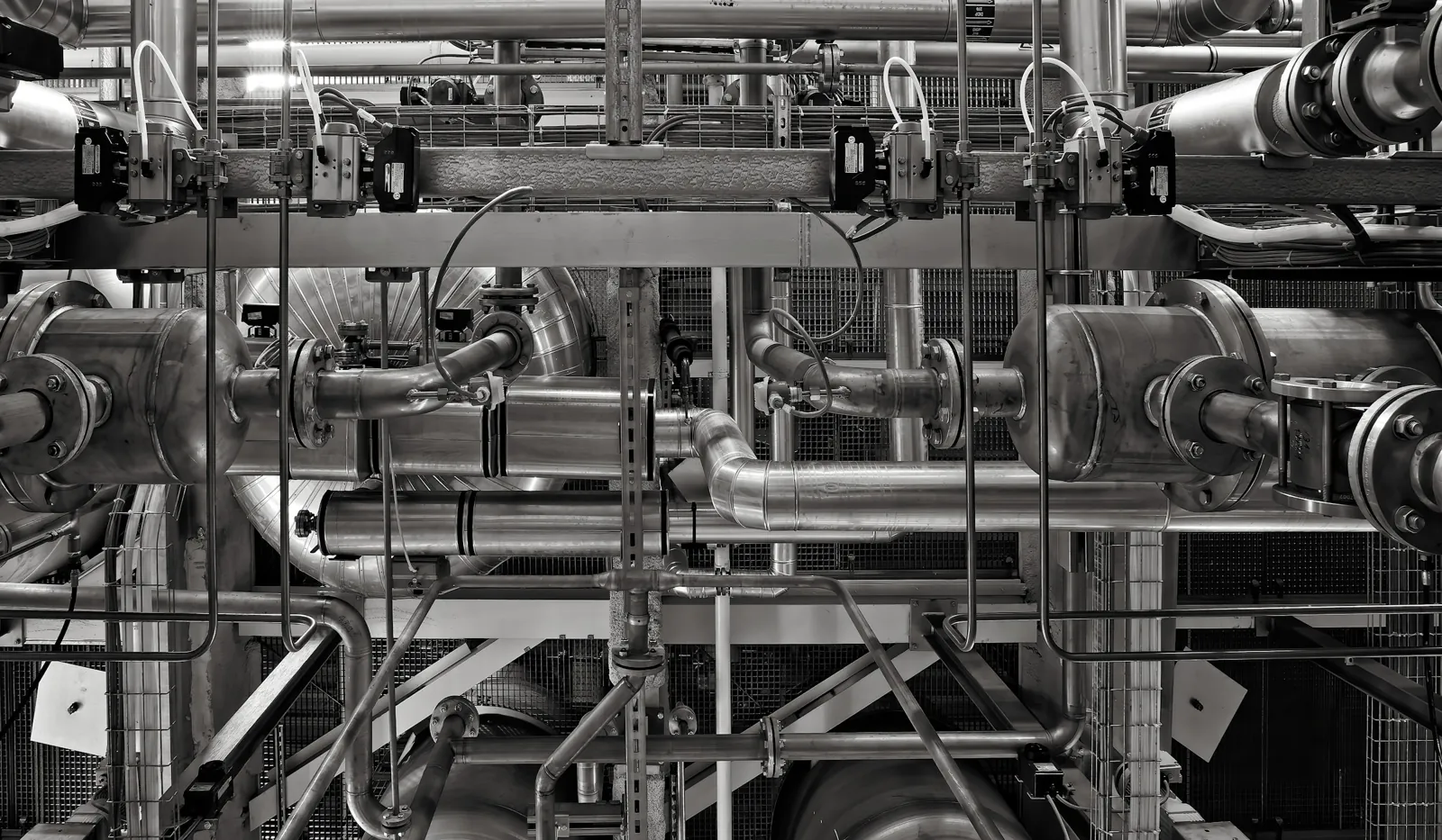
Power & cooling · design targets
Engineered forBlackwell-class density.
Proposed design targets, confirmed against your reference architecture before anything is ordered.
- Initial IT power
- Up to 5 MW site capacity; IT allocation phased per partner
- Expansion
- 10 MW, then up to 15 MW, subject to utility approval
- Air-cooled racks
- 15–40 kW per rack — inference, RTX PRO 6000, CPU, storage
- Liquid-cooled racks
- 40–80 kW per rack for HGX H100 / H200 / B200; 120–140 kW per rack for GB200 NVL72
Liquid cooling, heat rejection, PUE, monitoring
- Liquid architecture
- Direct-to-chip with in-row CDUs and a facility water loop; N+1, then 2N pumps
- Heat rejection
- Existing AC and chillers plus backup units; free-cooling hours where climate permits
- PUE
- Design target ≤ 1.3 at full liquid-cooled load
- Monitoring
- Real-time DCIM — per-rack power, inlet temperature, leak detection
Compute platforms · indicative
The GPU mixyou need.
Indicative support for current and next-generation NVIDIA platforms. The final mix is agreed with each partner.
Final mix
Agreed with each partner, against the workload.
- Day 1
RTX PRO 6000 Blackwell
Inference, visual compute, enterprise AI
- Approx. power
- 600 W / GPU
- Cooling
- Air
- Day 1
H100 (HGX 8-GPU)
Training and inference, mature software stack
- Approx. power
- 700 W / GPU
- Cooling
- Air or liquid
- Day 1
H200 (HGX 8-GPU)
Large-model inference, memory-bound training
- Approx. power
- 700 W / GPU
- Cooling
- Air or liquid
- With DLC fit-out
B200 (HGX 8-GPU)
Frontier training, high-throughput inference
- Approx. power
- 1,000 W / GPU
- Cooling
- Liquid preferred
- With DLC fit-out
GB200 NVL72
Rack-scale training and reasoning inference
- Approx. power
- 120–140 kW / rack
- Cooling
- Liquid required
- Roadmap, 10–15 MW phase
Next generation
Blackwell Ultra and Rubin-class systems
- Approx. power
- Higher rack density
- Cooling
- Liquid
CPU nodes
CPU nodes (AMD EPYC, Intel Xeon or NVIDIA Grace) are sized to the partner's head-node and storage ratio.
Indicative support for current and next-generation NVIDIA platforms. The final mix is agreed with each partner; CPU nodes (AMD EPYC, Intel Xeon or NVIDIA Grace) are sized to the partner's head-node and storage ratio.
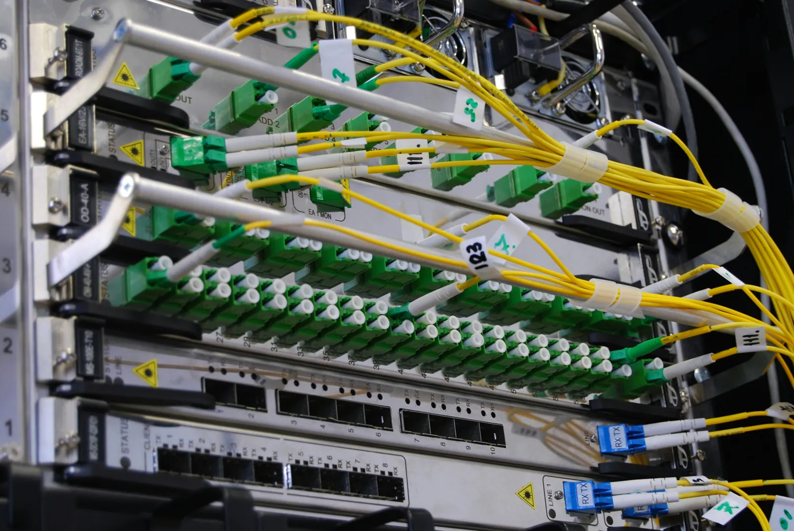
Network & interconnect · proposed
Non-blocking fabrics,to your reference design.
Proposed architecture. InfiniBand or Ethernet / RoCE is selected to the partner's standard.
Non-blocking
1:1 subscription in the compute fabric
Low latency
Sub-microsecond switch latency on InfiniBand
Validated
NCCL all-reduce benchmarks at acceptance
Redundant
Dual-homed spines and diverse fibre paths
The proposed architecture
- External connectivity
- Diverse carrier entries across multiple UAE carriers; private interconnect to the regional edge; DDoS protection
- Front-end / storage
- 100–400 GbE Ethernet; high-performance parallel storage; tenant VRF segmentation
- Compute fabric
- NVIDIA Quantum-2 / X800 InfiniBand or Spectrum-X RoCE; 400–800 Gb/s per GPU; rail-optimised, non-blocking fat tree
- In-node / in-rack
- NVLink — 900 GB/s (Hopper) to 1.8 TB/s (Blackwell) per GPU; NVL72 as a single NVLink domain
- Out-of-band
- Isolated OOB network for BMC, PDUs and CDUs; jump-host access only
Acceptance & commissioning
Handed over onlywhen it is proven.
Five-level commissioning, then AI-specific cluster validation. Capacity is in service because it passed — not because it is installed.
- Step 1 · Factory & site
L1–L3
FAT witness, delivery inspection, component start-up checks
- Step 2 · Systems test
L4
Power, cooling and CDU functional tests, per system
- Step 3 · Integrated (IST)
L5
Full-load bank, utility-fail and failover scenarios
- Step 4 · GPU validation
Burn-in
72h+ stress, NVIDIA DCGM diagnostics, ECC and thermal
- Step 5 · Performance
Cluster
HPL, NCCL all-reduce, MLPerf training and inference
Proposed acceptance criteria
- Benchmarks within an agreed tolerance of vendor reference results
- Zero critical hardware faults during burn-in
- Fabric bandwidth at line rate
- Integrated systems test passed at full design load
- Witnessed by partner engineers, with full test reports
Commercial models
Four waysto contract it.
The structure changes who owns the hardware and who runs it. The building, the power and the jurisdiction do not change.
Wholesale colocation
Powered shell
You deploy your own hardware into dedicated, powered and cooled halls.
Per kW / month, committed
Reserved
Dedicated GPU capacity
Qode Core procures and operates GPUs to your specification, reserved exclusively for you.
Per GPU-hour, take-or-pay
Bare metal
Managed cluster
A turnkey cluster with fabric, storage, monitoring and 24/7 operations.
Per GPU-hour plus managed services
In-country
Sovereign extension
In-country capacity for your own sovereign and regulated customers in the UAE.
Bespoke, multi-year
Term options of 3–5 years, with expansion rights over the 10–15 MW phases and a right of first refusal on new capacity.
Optional AI services on top — indicative
| AI service | What it adds | Indicative model |
|---|---|---|
| HZ AI orchestration | Higher utilisation; burst and surplus capacity monetised; one telemetry view | Revenue share per GPU-hour |
| Tynapse trust layer | Regulated tenants deploy AI agents with real-time guardrails and audit evidence | Per-workload subscription |
| QODE Cortex | Faster time to production for AI, GenAI, agentic and IoT workloads, on Lorgan's Enigma and Ellie | Platform subscription + delivery |
| Arabic AI layer | Arabic-language models, retrieval and pages for Arabic-speaking users | Managed service |
| University AI Hub | A pipeline of new AI ventures and talent anchored in the UAE | Co-commercialisation per venture |
Partnership roadmap
From agreementto Tier IV capacity.
Indicative, from a signed term sheet. The real dates depend on GPU lead times and on your specification.
Months 0–3
Design & procure
- Joint requirements workshop
- Reference architecture sign-off
- GPU, network and DLC orders placed
- Security and compliance gap review
Months 3–6
Tier III go-live
- Fit-out and L1–L5 commissioning
- GPU burn-in and cluster benchmarks
- Partner acceptance and handover
- First capacity in service
Month 6
Tier IV upgrade
- 2N power and cooling paths live
- Tier IV certification process
- Commitments step up to Tier IV levels
- Scale toward the full 5 MW
Month 12+
Expand
- 10 MW phase activated
- Next-generation GPU platforms
- Pathway to 15 MW
- Additional partner halls
Co-design
One workshop.Four decisions.
01
Capacity
Megawatts, phasing, rack density and the GPU platforms you need, from 5 MW toward 15 MW.
02
Model
Powered shell, dedicated GPU, managed cluster or sovereign extension — plus burst capacity.
03
AI services
Which layers to add: HZ AI orchestration, the Tynapse trust layer, QODE Cortex, Arabic AI.
04
Growth
University AI Hub ventures, internships, talent and regional go-to-market.

Co-design
Design yourcapacity blueprint.
Four decisions shape a Qode Core deployment. We work through them with you in one joint workshop, and leave it with phase one reserved.